|
|
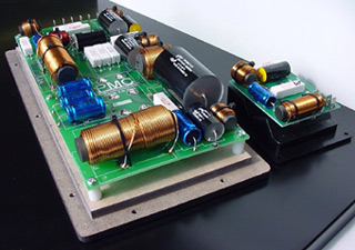
| June 15, 2003 Sound and Music: Crossover Networks The last chapter of this saga looked at three-way speakers, but could equally well have referred to them as "multi-ways," since the same principles apply to speakers with more than three ways. KEF’s new Reference 207, for example, uses a full five-way driver line-up. There are several obvious advantages in the multi-way approach, but significant disadvantages, too. On the plus side, sharing the available amplifier power between several drive units will increase the power handling, will allow each driver to be optimized to a more specialist role across a narrower band, and should help maintain a more consistent directivity across the band (improving the overall power response). The downside comes in the sheer complexity of the beast, and the number of components that have to be used in the crossover network that splits the incoming signal into the relevant bands for feeding the various drivers. So how does a crossover network operate? It’s actually quite simple, in theory at least, though the practicalities are altogether more complex. The raw materials or building blocks consist of three basic components: inductors (also known as chokes), capacitors, and resistors. Used singly or in combinations with the correct values, these act as filters that can be used either to block or to pass (and hence to roll-off or roll-on) signals in specific sectors of the audio band. Passing an audio signal through a capacitor will block the low frequencies; passing it through an inductor will block the high frequencies. (An inductor is basically just a coil of wire, so the voice coil of any regular drive unit will also possess inherent inductance.) Resistors are frequency neutral, merely reducing the level of all frequencies equally. At the actual acoustic crossover point between any two drivers, both should ideally be producing half their "normal" output, so that the two sum together to maintain a constant output level through the transition. That, however, assumes that both are time-aligned and operating in phase with each other, which is a crucial factor because crossover filters invariably shift relative phase as well as affecting amplitude (loudness) with frequency. Phase relationships are a vital part of crossover design, because the output of two drivers operating in phase with each other will add, whereas two drivers mounted close together and operating out of phase will tend to cancel each other out, and create a null. For a simple two-way speaker, the requirement is to roll-off the bass/midrange driver at the same time as the tweeter is being brought into play, placing the crossover point itself normally somewhere around 2-4kHz. The very simplest form of network uses just a single capacitor in the feed to the tweeter, while relying upon the natural roll-off of the bass/mid driver (a combination of mechanical decoupling and electrical inductance). This is attractive from the point of view of simplicity, but not easy to implement, relying on careful initial drive-unit design and precision quality control in production. Crossover networks are defined by the number of active elements used, or their order. That single capacitor in line (i.e., in series) with the tweeter is known as a first-order network, and provides a relatively gentle (6dB/octave) "roll-on," plus a modest (90 degree) phase shift. Adding a second element -- this time by placing an inductor across (i.e., in parallel with) the tweeter, and after the in-line capacitor -- will create a second-order network. Whereas placing a capacitor in series directly blocks the low frequencies from reaching the tweeter (which is vital, to prevent possible damage when meaty bass notes can easily destroy a delicate tweeter!), placing a choke (which passes low but not high frequencies) in parallel serves similar ends, because the low frequencies will pass through the choke and therefore bypass the tweeter. Provided the capacitor and choke have the correct values, the two effects will add, giving twice the roll-on rate (12dB/octave) and twice the phase shift (180 degrees).
Adding a second capacitor between one leg of the inductor and the tweeter itself will create a third-order network, with 18dB/octave slopes and a 270-degree phase shift, while introducing a second inductor ups it to fourth order, with relatively steep 24dB/octave slopes and a full-cycle 360-degree phase shift. Simplifying the crossover network to as few components as possible is obviously an advantage, if only because all components have some deleterious effect on sound quality. However, there are also less-obvious corresponding disadvantages. A simple first-order network can be made to work effectively, and does promise maximum transparency, but the gentle filter slopes have two negative implications. First and most importantly it means that the drive units must remain linear, well behaved, and free from significant resonance effects until well outside their nominal operating bands. Secondly it means that there will be a wide overlap region between the two drivers concerned, during which sound will simultaneously emanate from two drivers with different dispersion patterns. To avoid these difficulties, most designs opt for rather steeper, higher-order filters, reducing the overlap and the risk of out-of-band driver problems. Adding extra components can impede the transparency, so it becomes that much more important to use the better-class components, such as polypropylene capacitors and air-cored inductors. The more complex the network, the more important the actual component quality, but also the more critical the exact component values become, as even very minor errors can be sufficient to mistune a third- or fourth-order filter. If crossing over from one driver to another is the prime task of the network -- which of course is why it’s called a crossover network -- there are other important functions, too. One is to match the relative loudness of different drive units -- often the tweeter output has to be reduced, usually with resistors, to match the bass/mid driver. The other task is to perform equalization. This can be quite dramatic and extreme in some instances, but it more usually consists of a subtle and delicate adjustment during the final voicing of the design, tweaking a component value or adding a damping resistor to compensate for limitations in the drivers and the geometry of their mounting arrangements. There’s much more one could write about crossover networks, and much that is still only partly understood. Certainly the significant performance improvements found in the latest B&W Nautilus and JMlab Utopia Be models owe a great deal to the work both companies have put into investigating the sonic qualities of crossover components and the subtler aspects of vibration and electromagnetic interactions. ...Paul Messenger
Ultra Audio is part of the SoundStage! Network. |